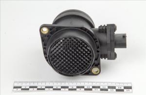
The Bosch mass air flow sensor with number 0 280 218 037 is used in cylinder air intake systems in the following vehicles:
LADA Kalina sedan (1118) 1.6 82 hp Petrol 2004 - present time
LADA Kalina station wagon (1117) 1.6 82 hp Petrol 2004 - present time
LADA Kalina hatchback (1119) 1.6 82 hp Petrol 2004 - present time
In the original factory spare parts catalogues, LADA goes by its number: 21083-1130010-10 and is its complete analogue.
Typically, the primary signs of a malfunctioning air flow sensor appear when the engine is not warmed up: the speed often fluctuates, making a cold start difficult, sometimes an inadequate response and jerking when pressing the gas pedal. But we recommend contacting a specialist to identify the malfunction; often these symptoms are characteristic not only of a non-functioning air flow sensor. However, any more or less experienced technician will be able to carry out diagnostics without any problems.
Our clients also often ask the question whether it is possible to clean the air flow sensor 0280218037 Bosch. In principle, cleaning is useful, do not forget that cleaning it is not difficult and it will not save you from problems if the sensor is completely dead. Based on our experience, we can advise measuring the wear level of the mass air flow sensor. It is necessary to check the ADC with the ignition on; the voltage value of the new air flow sensor is around 1.0 volts. If the flow meter gives 1.04-1.05, you can safely throw it in the trash, it has already served its purpose. If 1.03 is enough, it will be enough for a short time.
You can find out the necessary information about the applicability of the BOSCH 0 280 218 037 mass air flow sensor specifically to your car from our operator by contacting him by phone. We provide a guarantee for all our products, including the air flow sensor, for 6 months, without any conditions. If the part does not help eliminate the problem, you can return it to us within two weeks from the date of purchase, while keeping the original packaging and receipt. We always have it in stock at the lowest possible market price. We deliver throughout Moscow and throughout Russia, to cities such as St. Petersburg, Novosibirsk, Ufa, Samara, Perm, Nizhny Novgorod, Yekaterinburg, and many others. By default, we use the service - airmail cash on delivery, which allows us to ensure delivery of goods in the shortest possible time.
The Bosch 116 mass air flow sensor or mass air flow sensor is a regulator designed to control the volume of air that enters the engine. This controller is one of the elements of electronic engine control systems with fuel injection. In this article we will try to answer the question of how models 116 and 037 differ.
[Hide]
Characteristic
On VAZ cars, the mass air flow sensor is mounted between the air filter element and the throttle hose. Today, products from the manufacturer Bosch are very popular among compatriots. Regardless of whether it is a universal Bosch sensor or, for example, spark plugs, quality from a German manufacturer can always give a head start to domestic products. Let's look at the main characteristics of regulators models 116 and 037.
116
DMRV 116 is designed to control and convert the air flow that enters the motor into voltage. The data transmitted by the regulator makes it possible to determine the operating mode of the power unit and calculate the cyclic filling of the cylinders with air flow. This filling is carried out in steady-state operating modes of the motor, which last no more than 0.1 seconds.
Let's look at the technical features that Bosch 0 280 218 116 has:
- the regulator operates on the principle of measuring air flow;
- the device provides accurate data, which ensures optimal fuel consumption;
- operating range varies from 8 to 550 kg/h;
- the output pulse level when measuring the range from 0 to 100% will be about 0.05-5 volts;
- As for power supply, the controller is powered from the vehicle’s electrical network, that is, 12 volts is enough for it;
- current consumption is about 0.5 ampere;
- the regulator can function normally in the operating range from 45 degrees below zero to 120 degrees;
- The service life of the Bosch 116 mass air flow sensor is about 3 thousand hours.
037
As for the mass air flow sensor 037 from Bosch, the technical features will be similar. The controller consists of two main elements - working and control, as well as a heating resistor device. The air that enters the engine cools one of the controllers, while the electronic module converts the temperature differences between the controllers. In the event that sensor 280 218 037 fails, its options will be performed by TPS.
As mentioned above, the technical features of the models are the same:
- the operating range for normal operation varies in the region of 8-550 kg/h;
- when operating correctly, the controller will provide accurate data, making it possible to achieve optimal gas mileage (of course, if the engine is running in normal mode);
- since the element is used in a car, it is logical that it should be powered by 12 volts;
- the controller consumes about 0.5 ampere of current;
- the part can operate normally both at 45 degrees below zero and at 120 degrees of heat, this is its operating range;
- service life is at least 3 thousand hours;
- unlike model 116, the new mass air flow sensor 037 during calculations can produce an error of 2.5 percent (both downward and upward).

What is the difference between sensors 037 and 116?
How can the regulators of these models differ from each other and is it possible to install 116 instead of 037? There are differences between these controllers, and the point is not in the MAF pinout. After all, if these models were the same, what would be the point of giving them different names?
So, how do the controllers differ from each other and is it possible to install model 116 instead of 037:
- The first difference that can be guessed based on the technical characteristics is that the 037 model can produce data with an error during operation. Of course, an error of 2.5% is not critical, but it does exist.
- Device 037 is intended for installation in VAZ 2111, 2112, 2123, 21214 cars, which are equipped with controllers M 1.5.4, January 5.1-5.1.3, etc.
- As for model 116, its use is relevant on Ladas 21114, 21124, 21214. Installation of this device is allowed on Kalina and Priora. Installation of the device is allowed on cars equipped with M 7.9.7 and January 7.2 controllers.
If you encounter a problem with the device not working, then when replacing it you need to install the same model that has already been installed. But it is worth considering that 037 is not a common option like 116, so it is more difficult to find. The latter, in turn, is more common, and its cost is lower.
Replacement is allowed, but experts do not recommend this. This is because these devices differ in their calibration, so in case of replacement, you will have to change the parameters of the control unit. And you can only get into the “brains” of a car if you understand what needs to be done and have minimal experience.
To ensure compliance with legal emission requirements and to avoid unnecessary fuel consumption, air and gasoline must be supplied to the engine in precisely measured proportions. This is done using a mass air flow sensor or volumetric flow sensor, which determines the exact amount of air entering the engine and transmits this data to the engine management system.
When the fuel crisis of 1972–73 made reducing fuel consumption a major technology development goal, Bosch introduced the K-Jetronic mechanical airflow metering system and the L-Jetronic electronically controlled petrol injection system. As an inventor, Bosch is still a leader in the development of technology for measuring volumetric and mass air flow.
Bosch film mass air flow sensors
Bosch film mass air flow sensors are equipped with the latest technology (eg temperature, humidity and pressure sensors) and electronic modules. In modern versions, they have become extremely reliable because they are less susceptible to contamination. Bosch film mass air flow sensors operate with the highest precision, making a significant contribution to reducing fuel consumption and emissions.
Replacing the mass air flow sensor
When your MAF sensor needs replacing, using top-notch Bosch quality always pays off. Bosch mass air flow sensors are perfectly tuned to your vehicle and ensure optimal efficiency that reduces fuel consumption.
For optimal operation of an injection internal combustion engine (hereinafter referred to as ICE), it is necessary to take into account how much air mixture enters the combustion chambers of the cylinders. Based on these data, the electronic control unit (hereinafter referred to as the ECU) determines the fuel supply conditions. In addition to information from the mass air flow sensor, its pressure and temperature are taken into account. Since mass air flow sensors are the most significant, we will consider their types, design features, diagnostic and replacement capabilities.
Purpose and explanation of the abbreviation
Flow meters, also known as volume meters or mass air flow meters (not to be confused with mass air flow meters and mass air flow sensors), are installed in diesel or gasoline-powered vehicles. The location of this sensor is not difficult to find, since it controls the air supply, you should look for it in the corresponding system, namely, after the air filter, on the way to the throttle valve (DZ).
The device is connected to the engine control unit. In cases where the mass air flow sensor is in a faulty condition or is missing, a rough calculation can be made based on the position of the air flow sensor. But with this measurement method it is impossible to ensure high accuracy, which will immediately lead to excessive fuel consumption. This once again indicates the key role of the flow meter in calculating the fuel mass supplied through the injectors.
In addition to information from the mass air flow sensor, the control unit also processes data coming from the following devices: camshaft sensor (camshaft sensor), DD (knock meter), remote sensor, cooling system temperature sensor, acidity meter (lambda probe), etc.
Types of mass air flow sensors, their design features and operating principle
Three types of VU meters are most widespread:
- Wire or thread.
- Film.
- Volumetric.
In the first two, the operating principle is based on obtaining information about the mass of the air flow by measuring its temperature. The latter may involve two accounting options:

 Vortex sensor design (widely used by Mitsubishi Motors)
 Designations:
- A – pressure measurement sensor to record the passage of the vortex. That is, the frequency of pressure and vortex formation will be the same, which makes it possible to measure the flow of the air mixture. At the output, using an ADC, the analog signal is converted to digital and transmitted to the ECU.
- B - special tubes that form an air flow similar in properties to laminar.
- C – bypass air ducts.
- D – column with sharp edges on which Karman vortices are formed.
- E – holes used to measure pressure.
- F – direction of air flow.
Wire sensors
Until recently, thread mass air flow sensor was the most common type of sensor installed on domestic cars of the GAZ and VAZ model range. An example of a wire flow meter design is shown below.

Designations:
- A – Electronic board.
- B – Connector for connecting the mass air flow sensor to the computer.
- C – CO adjustment.
- D – Flow meter housing.
- E – Ring.
- F – Platinum wire.
- G – Resistor for temperature compensation.
- N – Ring holder.
- I – Electronic board casing.
Operating principle and example of a functional diagram of a filament VU meter.
Having understood the design of the device, let's move on to the principle of its operation, it is based on the hot-wire method, in which a thermistor (RT), heated by the current passing through it, is placed in the air flow. Under its influence, the heat transfer changes, and, accordingly, the resistance RT, which makes it possible to calculate the volumetric flow rate of the air mixture? using King's equation:
I 2 *R=(K 1 +K 2 * ⎷ Q )*(T 1 -T 2) ,
where I is the current passing through RT and heating it to temperature T1. In this case, T 2 is the ambient temperature, and K 1 and K 2 are constant coefficients.
Based on the above formula, you can derive the volumetric air flow rate:
Q = (1/K 2)*(I 2 *R T /(T 1 – T 2) – K 1)
An example of a functional diagram with bridge connection of thermoelements is shown below.

Designations:
- Q - measured air flow.
- U – signal amplifier.
- R T - wire thermal resistance, as a rule, is made of platinum or tungsten filament, the thickness of which is in the range of 5.0-20.0 microns.
- R R – temperature compensator.
- R 1 -R 3 – ordinary resistances.
When the flow velocity is close to zero, the RT is heated to a certain temperature by the current passing through it, which allows the bridge to be kept in equilibrium. As soon as the flow of the air mixture increases, the thermistor begins to cool, which leads to a change in its internal resistance, and, as a result, an imbalance in the bridge circuit. As a result of this process, a current is generated at the output of the amplifier unit, which partially passes through the temperature compensator, which leads to the release of heat and makes it possible to compensate for its loss from the flow of the air mixture and restores the balance of the bridge.
The described process allows you to calculate the flow rate of the air mixture based on the amount of current passing through the bridge. In order for the signal to be perceived by the ECU, it is converted into a digital or analog format. The first allows you to determine the flow rate by the frequency of the output voltage, the second - by its level.
This implementation has a significant drawback - a high temperature error, so many manufacturers add a thermistor similar to the main one to the design, but do not expose it to air flow.
During operation, dust or dirt deposits may accumulate on the wire thermistor; to prevent this, this element is subjected to short-term high-temperature heating. It is performed after the internal combustion engine is turned off.
Film air meters
A film MAF works on the same principle as a filament one. The main differences lie in the design. In particular, silicon crystal is used instead of platinum filament resistance wire. It is coated with several layers of platinum plating, each of which plays a specific functional role, namely:
- Temperature sensor.
- Thermal resistances (usually there are two of them).
- Heating (compensation) resistor.
This crystal is installed in a protective casing and placed in a special channel through which the air mixture passes. The geometry of the channel is designed in such a way that temperature measurements are taken not only from the input flow, but also from the reflected one. Thanks to the created conditions, a high speed of movement of the air mixture is achieved, which does not contribute to the deposition of dust or dirt on the protective housing of the crystal.

Designations:
- A – Flow meter body into which the measuring device (E) is inserted.
- B – Contacts of the connector that connects to the ECU.
- C – Sensitive element (silicon crystal with several layers of coating, placed in a protective casing).
- D – Electronic controller, with the help of which preliminary processing of signals is carried out.
- E – Body of the measuring device.
- F - Channel configured to take thermal readings from the reflected and input flow.
- G – Measured flow of air mixture.
As mentioned above, the operating principles of filament and film sensors are similar. That is, the sensitive element is initially heated to temperature. The flow of the air mixture cools the thermoelement, which makes it possible to calculate the mass of the air mixture passing through the sensor.
As in filament devices, the output signal can be analog or converted to digital format using an ADC.
It should be noted that the error of filament VU meters is about 1%; for film analogues this parameter is about 4%. However, most manufacturers have switched to film sensors. This is explained both by the lower cost of the latter and by the expanded functionality of the ECUs that process information from these devices. These factors overshadowed the accuracy of the instruments and their speed.
It should be noted that thanks to the development of flash microcontroller manufacturing technology, as well as the introduction of new solutions, it was possible to significantly reduce the error and increase the performance of film structures.
Interchangeability
This issue is quite relevant, especially taking into account the cost of original products from the imported automobile industry. But it’s not so simple here; let’s give an example. In the first production models of the Gorky Automobile Plant, the injection Volgas were equipped with a BOSCH air flow sensor. Somewhat later, imported sensors and controllers replaced domestic products.
 A – imported filament air flow sensor manufactured by Bosh (pbt-gf30) and its domestic analogues B – JSCB “Impuls” and C – APZ
 Structurally, these products were practically no different with the exception of several design features, namely:
- The diameter of the wire used in a wirewound thermistor. Bosch products have a diameter of 0.07 mm, and domestic products have a diameter of 0.10 mm.
- The method of fastening the wire differs in the type of welding. For imported sensors this is resistance welding, for domestic products it is laser welding.
- Shape of a thread thermistor. Bosh has a U-shaped geometry, APZ produces devices with a V-shaped thread, and products from JSC Impulse are distinguished by the square shape of the thread suspension.
All the sensors given as an example were interchangeable until the Gorky Automobile Plant switched to film analogues. The reasons for the transition were described above.
 Film air flow sensor Siemens for GAZ 31105
 It makes no sense to give a domestic analogue to the sensor shown in the figure, since outwardly it is practically no different.
It should be noted that when switching from filament devices to film devices, most likely, it will be necessary to change the entire system, namely: the sensor itself, the connecting wire from it to the ECU, and, in fact, the controller itself. In some cases, the control can be adapted (reflashed) to work with another sensor. This problem is due to the fact that most filament flowmeters send analog signals, while film flowmeters send digital signals.
It should be noted that the first production VAZ cars with an injection engine were equipped with a filament air flow sensor (made by GM) with a digital output; examples include models 2107, 2109, 2110, etc. Now they are equipped with air flow sensor BOSCH 0 280 218 004 .
To select analogues, you can use information from official sources or thematic forums. As an example, below is a table of the interchangeability of mass air flow sensors for VAZ cars.

The presented table clearly shows that, for example, the MAF sensor 0-280-218-116 is compatible with VAZ 21124 and 21214 engines, but is not suitable for 2114, 2112 (including those with 16 valves). Accordingly, you can find information on other VAZ models (for example, Lada Granta, Kalina, Priora, 21099, 2115, Chevrolet Niva, etc.).
As a rule, there will be no problems with other brands of cars of domestic or joint production (UAZ Patriot ZMZ 409, Daewoo Lanos or Nexia), choosing a replacement mass air flow sensor for them will not be a problem, the same applies to products of the Chinese automobile industry (KIA Ceed, Spectra, Sportage etc.). But in this case, there is a high probability that the MAF pinout may not match; a soldering iron will help correct the situation.
The situation is much more complicated with European, American and Japanese cars. Therefore, if you have a Toyota, Volkswagen Passat, Subaru, Mercedes, Ford Focus, Nissan Premiere P12, Renault Megane or another European, American or Japanese car, before replacing the mass air flow sensor, you need to carefully weigh all the solution options.
If you are interested, you can search online for an epic about an attempt to replace the “native” air meter with an analogue on a Nissan Almera H16. One attempt resulted in excessive fuel consumption even at idle.
In some cases, searching for an analogue one will be justified, especially if you take into account the cost of the “native” VU meter (for example, the BMW E160 or Nissan X-Trail T30).
Functionality check
Before diagnosing the mass air flow sensor, you need to know the symptoms that allow you to determine the degree of performance of the MAF (abbreviation for the English name of the device) sensor in the car. We list the main symptoms of a malfunction:
- The consumption of the fuel mixture has increased significantly, while at the same time acceleration has slowed down.
- The internal combustion engine idles with jerks. In this case, a decrease or increase in speed may be observed in idle mode.
- The engine does not start. Actually, this reason in itself does not mean that the flow meter in the car is faulty; there may be other reasons.
- A message appears about a problem with the engine (Cheeck Engine)
 Example of the "Cheeck Engine" message displayed (marked in green)
 These signs indicate a possible malfunction of the mass air flow sensor; in order to accurately determine the cause of the failure, diagnostics must be performed. It's easy to do it yourself. Connecting a diagnostic adapter to the ECU (if this option is possible) will help to significantly simplify the task, and then determine the serviceability or malfunction of the sensor using the error code. For example, error p0100 indicates a fault in the flow meter circuit.

But if you need to carry out diagnostics on domestic cars manufactured 10 years ago or more, then checking the mass air flow sensor can be carried out in one of the following ways:
- Testing while moving.
- Diagnostics using a multimeter or tester.
- External inspection of the sensor.
- Installation of a similar, known-good device.
Let's consider each of the listed methods.
Testing while driving
The easiest way to check is by analyzing the behavior of the internal combustion engine with the MAF sensor disabled. The algorithm of actions is as follows:
- You need to open the hood, turn off the flow meter, close the hood.
- We start the car, and the internal combustion engine goes into emergency mode. Accordingly, a message indicating a problem with the engine will appear on the dashboard (see Fig. 10). The amount of fuel mixture supplied will depend on the position of the remote control.
- Check the dynamics of the car and compare it with what it was before the sensor was turned off. If the car has become more dynamic and power has also increased, then this most likely indicates that the mass air flow sensor is faulty.
Note that you can continue driving with the device turned off, but this is highly not recommended. Firstly, the consumption of the fuel mixture increases, and secondly, the lack of control over the oxygen regulator leads to increased pollution.
Diagnostics using a multimeter or tester
Signs of a malfunction of the mass air flow sensor can be identified by connecting the black probe to ground, and the red probe to the sensor signal input (the pinout can be found in the device data sheet, the main parameters are also indicated there).

Next, we set the measurement limits to 2.0 V, turn on the ignition and take measurements. If the device does not display anything, you need to check that the probes are connected correctly to ground and the flow meter signal. Based on the readings of the device, you can judge the general condition of the device:
- A voltage of 0.99-1.01 V indicates that the sensor is new and working properly.
- 1.01-1.02 V – used device, but its condition is good.
- 1.02-1.03 V - indicates that the device is still operational.
- 1.03 -1.04 the condition is approaching critical, that is, in the near future it is necessary to replace the mass air flow sensor with a new sensor.
- 1.04-1.05 – the device’s resources are almost exhausted.
- Over 1.05 - a new mass air flow sensor is definitely needed.
That is, you can correctly judge the state of the sensor by the voltage; a low signal level indicates an operational state.
External inspection of the sensor
This diagnostic method is no less effective than the previous ones. All that is necessary is to remove the sensor and assess its condition.
 Inspect the sensor for damage and fluid
 Characteristic signs of a malfunction are mechanical damage and liquid in the device. The latter indicates that the oil supply system to the engine is not adjusted. If the sensor is very dirty, the air filter should be replaced or cleaned.
Installing a similar, known-good device
This method almost always gives a clear answer to the question of the sensor’s performance. This method is quite difficult to implement in practice without purchasing a new device.
Briefly about the renovation
As a rule, MAF sensors that have become unusable cannot be repaired, except in cases where they require washing and cleaning.
In some cases, it is possible to repair the volumetric air flow sensor board, but this process will not prolong the life of the device for long. As for the boards in film sensors, without special equipment (for example, a programmer for a microcontroller), as well as skills and experience, it is pointless to try to restore them.
Dear customers, in order to avoid errors when sending a mass air flow sensor (MAF), indicate your car model, year of manufacture and number of valves in the “Comment” line.
Mass air flow sensor (MAF)116 BOSCH - hot-wire type.
Structurally, this type of sensorshas a sensitive element, a thin mesh (membrane) based on silicon, which is installed in the intake air flow. The grid contains a heating resistor and two temperature sensors, which are installed before and after the heating resistor.
The output signal of the mass air flow sensor is a DC voltage within 1...5 V. The value depends on the amount of air passing through the sensor. While the engine is running, the intake air cools the part of the mesh located in front of the heating resistor. The temperature sensor located in front of the resistor is cooled, and the sensor located behind the heating resistor maintains its temperature by heating the air. The differential signal from both sensors makes it possible to obtain a characteristic curve depending on the amount of air flow.
The ECU analyzes the mass air flow sensor signal and, using its data tables, determines the duration of the injector opening pulse, which corresponds to the mass air flow signal.
Mass air flow sensor 116 BOSCH has a built-in air temperature sensor (ATS), the readings of which are used in the distributed fuel injection system of the car 21214 and distributed fuel injection systems under EURO-3 toxicity standards. The sensitive element of the DTV is a thermistor (a resistor that changes resistance depending on temperature) - installed in the flow of passing air. The controller supplies 5V voltage through a fixed resistor located inside the controller. The controller calculates the temperature based on the voltage drop across the sensor. As the temperature increases, the voltage decreases. Based on sensor readings, the controller calculates the duration of the injector opening pulses.
The mass air flow sensor is installed between the air filter and the throttle pipe.
Other article numbers of the product and its analogues in catalogues: 21083-1130010-20.
Product Features:
Mass air flow sensor(catalog designation"BOSCH" 0 280 218 116) ,designed to convert the air flow entering the engine into DC voltage. The sensor information allows you to determine the engine operating mode and calculate the cyclic filling of the cylinders with air at steady engine operating conditions, the duration of which exceeds 0.1 seconds.
VAZ 2105-07 (Classic 1.6L injection), VAZ 2108-21099, VAZ 2110-2112; VAZ 2113-2115, VAZ 1118-1119, VAZ 2170-2172, VAZ 21214, 2123 Euro-2, Euro – 3 (from VAZ 2006 onwards)
Specifications:
- Optimal fuel consumption is ensured in all engine operating modes due to high accuracy and stability of output characteristics.
Using the thermal principle of air flow measurement.
The range of measurement of mass air flow is from 8 to 550 kg/h.
The measurement error of the mass flow of the new sensor is +/- 2.5%.
The magnitude of the output signal when measuring the flow range from 0 to 100% is from 0.05 to 5 V.
The sensor is powered from the vehicle's on-board network with a rated voltage of 12 V.
The supply voltage range is from 7.5 to 16 V.
Current consumption (at supply voltage from 7.5 to 16 V) - 0.5 A.
Operating temperature range - from -45° to +120° C.
MTBF, no less than 3000 hours.
How to identify the problem
Just COMPARE and BE SURE!!!